
I guess we will have to call this a latent post as it is out of chronological order. I undertook this project almost exactly one year ago but I didn’t have this website at that time. Work began in November 2022 and was completed in January 2023.
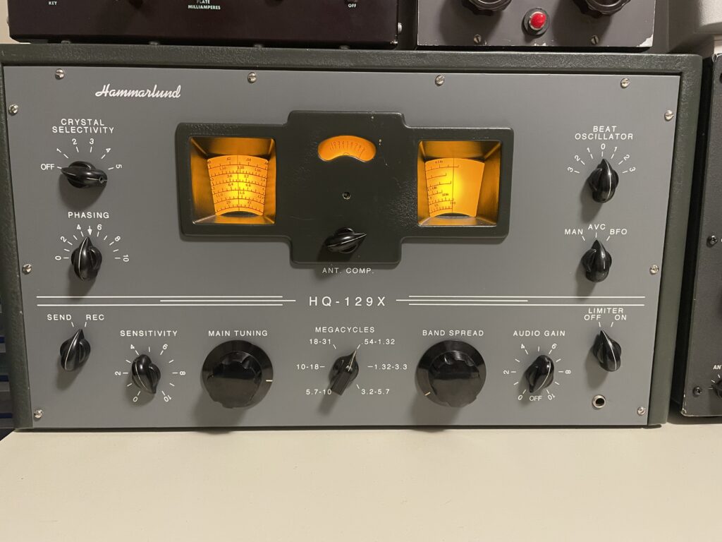
I had acquired a complete, working and cosmetically very good Hammarlund HQ-129X in the spring of 2022 at a local ham radio flea market. It spoke to me because I love Hammarlund radios, it’s the last of their octal tube based receivers and I didn’t have a vacuum tube based general coverage receiver. The picture above is it as it looked when I got it.
This was my first radio repair/restoration project undertaken in my newly re-constructed ham shack. The front panel on this radio had already been replaced/refurbished, the knobs were all there and in good shape and the chassis was very clean. That made for a great starting point. So what did it need?
Firstly, both the Main Tuning and Band Spread dials were discoloured from decades of sun shining on one side of them and the dial lamps shining on the other. Secondly, the unit was still in possession of all of its’ original electrolytic and paper capacitors. Thirdly, a check of the tubes found that the 5U4 rectifier was on its’ last legs and the 6SN7 audio pre-amp was a little weak.
And of course a full RF and IF alignment would be the last step. I could tell that the radio was out of alignment. The calibration of the main tuning dial was off and engaging the crystal filter clobbered the signal badly. Clearly the IF and the crystal filter frequency were not in agreement.
I ordered new tuning dials from Radio Daze and they were perfectly correct save for one small detail which I will get into later. I also ordered a re-cap kit from Hayseed Hamfest. This was a matter of convenience. I could have pieced together a re-cap kit myself but this saved me a bunch of work and I found the price reasonable. I also ordered the two tubes I needed to replace plus one complete set of spares.
Now the fun began!
Vacuum tubes
Using my trusty but simple B&K 606 tube tester I checked all the tubes. The 5U4 full-wave rectifier barely moved the needle. So that was bad. The 5U4 was running awfully hot yet the radio did function. It was amazing how well it worked, in fact. The first audio amplifier, a 6SN7, was on the weak side so it had to go, too.
I acquired a full set of NOS spares plus one 6SN7 and one 5U4. I installed the new set of tubes and took the old ones and put them into inventory. I now had all NOS tubes in the radio and one complete set of spares on hand.
Capacitors
The electrolytic caps in the power supply had to go (four caps in one can) and so did the 27 paper/wax caps throughout the radio. Luckily, Hayseed Hamfest sells a re-cap kit for this radio.
Once the capacitors arrived I started with the big quad-electrolytic can in the power supply. It was a bit tight as the new capacitor was physically longer than the original by about 1″. Then it was on to all the rest of the smaller caps. I did 5 or 6 a night until that work was complete. If I got to a point in the evening where it wasn’t fun and felt like work I would stop work and pour a whisky.
The caps on the RF/IF side of the radio were easy, lots of room there to work. The caps on the PS and AF side of the radio were harder due to tight quarters, especially the ones in the BFO can. And there were several small dead insects inside the BFO can. How did they get there? It is sealed unless the 6SJ7 is removed thus exposing the hole in the octal base. That must have been it.
I found this part of the refurbishment very enjoyable. I made only one mistake. Given the amount of things I did I thought that was pretty good. Taking out the large, old paper capacitors opened up a lot of room to install the new small polystyrene caps. All the small yellow polystyrene caps look right at home in the now seemingly cavernous underbelly of the Hammarlund chassis.
Tuning dials
The tuning dials were very yellowed in parts, even brown in some areas. I didn’t know when I bought this radio one could get new tuning dials from Radio Daze. Once I learned that I ordered a set. This radio was going to look like it did when it was new!
I removed the old tuning dials and noted that they were attached to their hubs with tiny copper rivets. I carefully drilled the wee rivets out and then set about figuring out how to mount the new dials. The holes were small and I needed something that was thin like the old rivets once installed. This was to avoid clearance issues with the dial stops.
A fellow in a forum said that he used some #2 hardware for this and it worked. Excellent! I’d never looked for #2 hardware (nuts, bolts, washers) but I figured our excellent local nut and bolt supply house could fix me up. Not so, I was told. They went down to #4 and had nothing smaller.
I located a source of #2 hardware online (The Bolt Depot) and ordered 100 each of #2-56 bolts (1/8″ long), nuts and washers (just in case). The shipping ($14) was more than the hardware ($13) and I now have a lifetime’s supply of #2 hardware. In brass. I figured a non-ferrous material (copper rivets) was used originally for a good reason so I stuck with that idea.
After bolting the new dials to their hubs and re-installing them into the radio I discovered two problems. One was that the #2 hardware was thicker than the old rivets were and they interfered with the dial stops when tuning. A thin washer on each tuning shaft shimmed them far enough away that they cleared the tuning stops.
The second was that the main tuning dial was not perfectly round and would bind against the body of the S meter as you tuned toward one end of the band. I solved this problem by attaching the dial’s hub to a 1/4″ drill bit in my variable speed hand drill and spinning it against some 400-grit sandpaper until it was rounder and ever so slightly smaller than when I started. I probably took off less than 1/64″ to make it fit.
That was the end of the mechanical challenges. Now back to the electronics!
Dial lamps
The radio has 3 dial lamps. One for each of the main tuning dial, S meter and band spread dial. These were #47 lamps with bayonet bases in sockets. Each socket had the old phenolic “button” in the base for the centre lamp contact.
One of the phenolic bases broke during disassembly, rendering the socket unusable so I decided to replace the old incandescent lamps with LED’s. This would have a couple of advantages. It would remove ~400 mA of load from the 6.3V heater winding on the transformer and it would remove the dial lamp heat from the tuning dials.
I am intolerant of 60 Hz flicker and so I designed a small half-wave DC power supply for the LEDs. Like so:
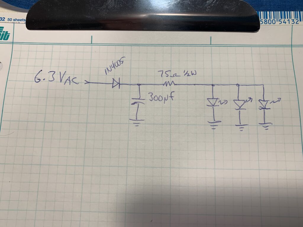
That was my first draft and not what finally ended up in the radio. I tweaked the values of the filter capacitor and current limiting resistor a bit to get it just right to deliver ~20mA of current to each LED.
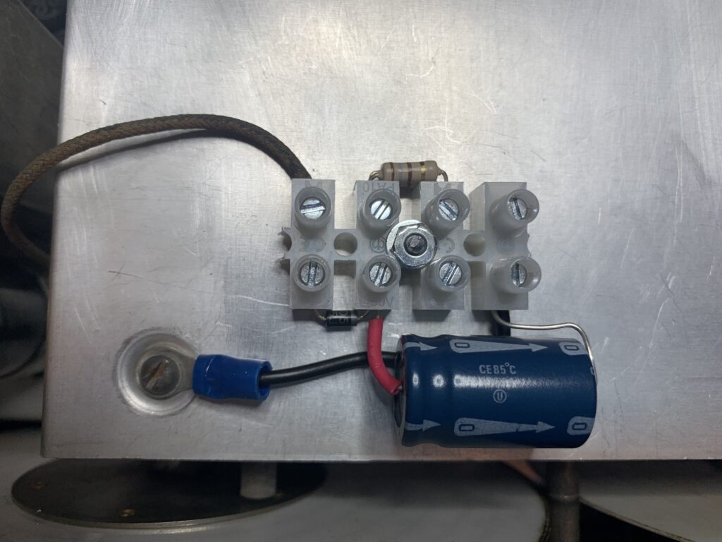
Here is the wee DC power supply for the LEDs installed on top of the tuning cover inside the radio right behind the main tuning dial. I used a chunk of leftover terminal strip to build it, because, well, you know, it was on hand. The LEDs are not yet connected. The 6.3 VAC enters stage left and you can follow it from there.
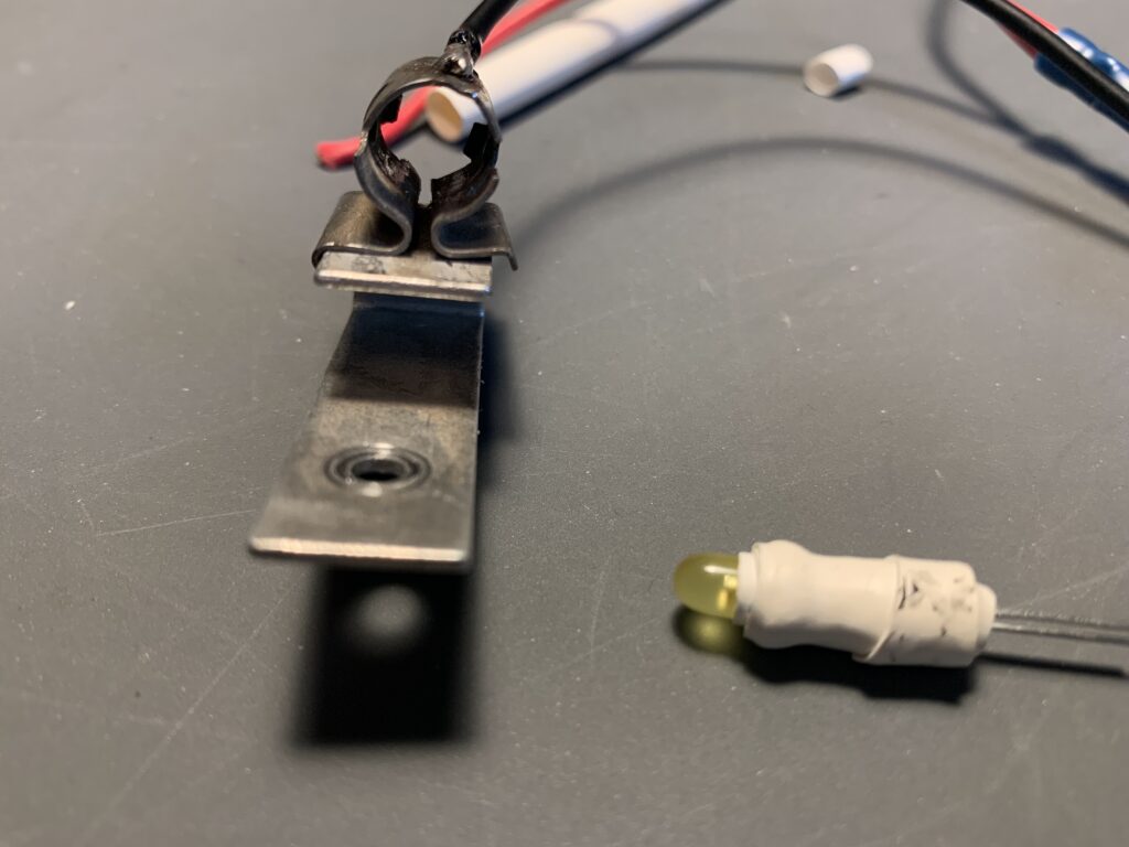
To install the LEDs in the old lamp sockets I wrapped each LED in concentric layers of heat shrink tubing, shrunk it on and added layers of ever-increasing diameters of tubing to get to the right size that would allow for a good friction fit inside the lamp socket housing.
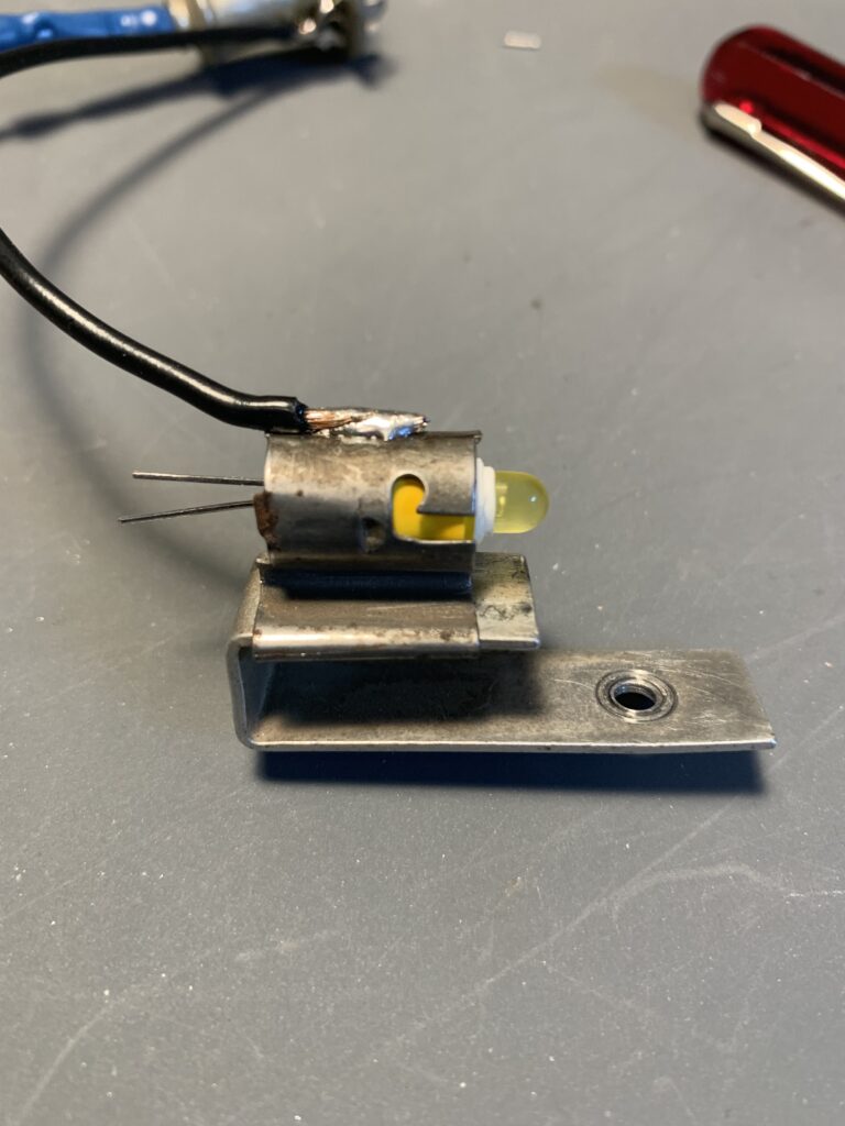

Once installed the new amber LEDs could not have looked better. They illuminated the dials and meter very nicely and were easy on the eyes. I was very pleased with the results and all using parts that were on hand.
New tuning knobs
The general consensus is that these radios have tuning and band spread knobs that are way too small. I agree, they really are. So I acquired some knobs that looked more appropriate and offered a more pleasurable tuning experience. I believe they are Raytheon knobs.
They’re a big improvement but they’re still a little too small. The newer Hammarlund radios corrected this ergonomic fault so I shall have to keep searching. In the mean time these will do. I kept the original knobs, of course, in case the next owner wants to put it back to original.
Full alignment
And now for the final and arguably most fun part of the project. All the electronics are in good shape, the power supply voltages look good, it’s time for a full alignment of the receiver.
I followed the Hammarlund manual for this. I am fortunate to have an excellent signal generator, an HP 8657A, which is also fully calibrated so I knew I’d end up with a good result. I also have an HP 5328A frequency counter, also properly calibrated, to help nail down the crystal filter frequency.
The IF comes first and there are three gain stages plus a crystal filter between two of them. The IF alignment goes like this:
- Working backwards from output to input peak each IF stage at 455 kHz
- Determine the exact frequency of the crystal in the filter (it’s very close to 455 kHz but it’s not exactly 455 kHz)
- Re-peak the IF stages, in reverse order again, to the crystal frequency learned above
The challenge with the IF is that the tightest crystal filter setting is 200 Hz and you therefore need to get your IF stages bang on to the crystal filter frequency. This is quite fiddly. Then it’s on to the RF alignment, which is quite straightforward but gets a bit fiddly on this higher bands. It gets pretty touchy above 15 MHz.
There is an adjustment for the S meter also. Like Collins and many others, Hammarlund also specifies that a reading of S9 corresponds to 50uV of signal. The BFO alignment is pretty easy, not that I will be using it, but I wanted all aspects of the radio to be proper.
A good alignment brought this radio to life again! It was operating beautifully and properly. It was sensitive, selective and the audio quality was excellent. Because it has a BFO and not a product detector it’s not the world’s best SSB rig but that’s not my intended use. This is my band-cruiser for AM signals. It excels at broadcast band DX and I do enjoy that.
I was more than pleased with the final results. Both the look of the radio and its’ performance are excellent. I should have taken more photos of the process.
The picture below is the unit after all work was completed. The blotchy appearance of the dial lamps is an artifact of the iPhone camera I used to take the photo. In reality there is just a nice, smooth gradient of warm amber illumination.