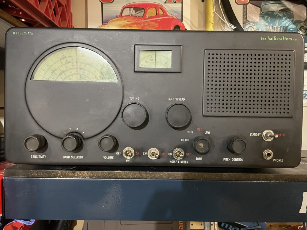
I recently acquired a Hallicrafters S-77A that needed a little work. I’ve been wanting to add a Hallicrafters radio to my collection and in particular I wanted one of the ones styled by the famed industrial designer Raymond Loewy (look him up!). I got lucky and this one just kind of fell into my lap. The photo above is what it looked like when I received it.
The S-77A is the AC/DC/Marine version of the S-40B. Because of this the S-77A units are far less common than the S-40B.
The radio had already had almost all of it’s old paper/wax capacitors replaced with just two left to be done. And all of the electrolytic capacitors in the power supply had been done except for one. The radio worked pretty well as it was. The audio quality was good, the dial calibration was pretty good and it seemed reasonably sensitive given what it is, that being Hallicrafters’ mid-level general coverage receiver in the early 1950’s. Better than the low-end S-38 but not as good as the high-end SX-42.
All but two of the tubes tested good on my B&K 606 Dynajet tube tester. The two tubes in the audio section were a little soft. The 6SC7 AF pre-amp and the 25L6 AF power amp. I didn’t have either one in my tube inventory so I acquired some.
The two dial lamps were also the wrong type. This was a problem in this radio because it is an AC/DC radio so the tube filaments are wired in series along with the dial lamps which have parallel resistors to allow the proper amount of current to flow in the series circuit (~325 mA in this case). So to maintain proper filament voltage you have to maintain the proper series current, meaning that the dial lamps need to be the correct GE type 47 which consume 150mA of current. The balance of the 325 mA flows through the resistor in parallel with the #47 lamp.
Replacing the four capacitors, the two tubes and the two dial lamps was all the electronics work that was needed. The knobs were pulled and soaked in hot soapy water and cleaned with a nylon bristle brush. 71 years of accumulated filth was thus removed. Three of the knobs had damaged set screws so those were replaced. The front panel was cleaned up while the knobs were off. Cosmetically the radio was in good shape and a little clean up made it look even better!
It’s an AC/DC radio so there is no power transformer. It’s a two-wire line cord and one side of the line is tied to the chassis, as it was made in 1952 long before the three wire grounded circuits were in use. So there is a 50/50 chance of the chassis being hot. I should probably put a polarized plug on it.
The main tuning and band spread dials were indexed and then full IF and RF alignments were performed. Actually, I aligned it twice. Once to learn the process on this radio and once more to make sure it was as good as it could be. The radio works well but one thing I noticed is that because the B+ is only half-wave rectified there is more ripple on it than there would be in a full-wave rectifier configuration. This can be heard as a 60 Hz hum on the audio when the AF gain is all the way down.
This appears to be normal for this design. I measured the ripple at ~3% which seems about right for an unregulated 1/2-wave supply. Unregulated full-wave supplies normally have about 2% ripple. And why is the PS only half-wave, you ask? It’s a side-effect of it being an AC/DC radio. It can be powered from 115V AC or DC. Or 230V AC or DC. Because of this, Hallicrafters wired the two diodes in the rectifier tube, a 25Z6, in parallel. Hence half-wave, hence more ripple.
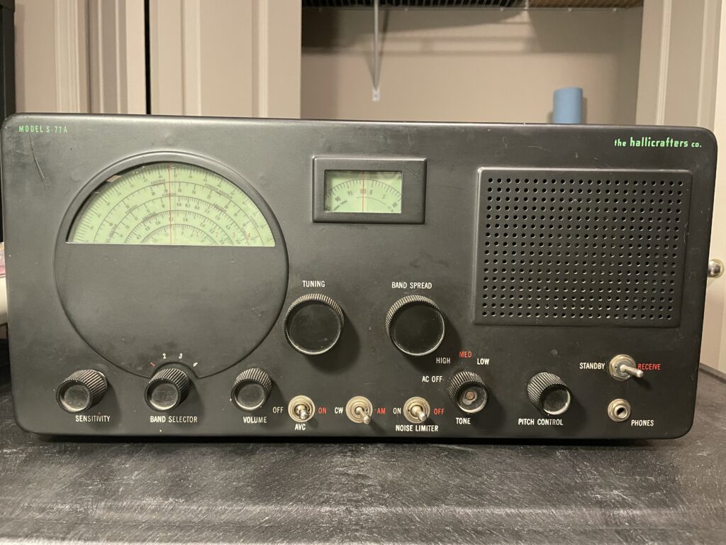
It’s working well now and it looks great. It’s primary use will be for AM broadcast band listening in my garage shop. Here’s a picture of it all done and in the garage shop: