
A couple of my friends have been experimenting with AllStarLink and it looked interesting to me so I thought I would join in the fun. I’ve never had a Raspberry Pi and this gave me a reason to get one.
My plan was to build a simplex AllStarLink node for use on the 70cm band. It would look like this when done:
Raspberry Pi <–> CM108 sound card <–> Interface <–> Motorola XPR 4550
This article is about the interface between the CM108 sound card and the Motorola mobile radio as it was the only piece needed to complete the project. There are commercial options but given how simple it is home-brewing seemed the best option. Much cheaper and way more fun than buying something. Plus I had everything I needed for it on hand other than a box to put it in.
I ordered a Raspberry Pi 4B kit and a CM108 USB sound card. The CM108 needs some hardware modification to be used for this. My pal Neil offered to do the mods to it. He has the equipment for SMD work so I just said yes.
I requested a node number from allstarlink.org. Then I installed and configured the HamVOIP software from hamvoip.org. Although I am a BSD guy I have been known to slum it in Linux-land on occasion.
I already had a Motorola XPR 4550 up on 70cm so my plan was to use that radio for this project. The only missing piece was an interface circuit to massage PTT and COR between the CM108 sound card and the Motorola. Transmit and receive audio would just be passed through between the sound card and radio as those levels are compatible and can be adjusted to suit from the HamVOIP software.
I wanted status indicators for PTT and COR and a buffer between the sound card and the Motorola. The wee sound card is a on the wimpy side in terms of driving anything. My preference is to run PTT and COR both active low on the radio. But the CM108 USB sound card must run with PTT active high due to the hardware hackery associated with getting a PTT signal out of the thing.
So I needed a non-inverting buffer for COR and an inverting buffer for PTT. A simple enough proposition. I used my two go-to transistors for this. A 2N3904 NPN transistor would take a high PTT from the CM108 and turn it into a low PTT into the Motorola while driving a red LED. A 2N3906 PNP transistor would be used to take low COR from the Motorola and send it on to the CM108 while driving a LED.
The Motorola XPR has a “switched B+” output (i.e. battery voltage) available on its’ accessory connector so I also needed a 78L05 voltage regulator to knock that down to 5V to power the interface circuitry. That would give signal levels that would be compatible between the CM108 and Motorola XPR.
On the bread board it came out like this:

The wires on the left go to the CM108 on the Raspberry Pi and the wires on the right go to the Motorola XPR. The red PTT LED is on the left with it’s transistor and the green COR LED is in the middle with it’s transistor. The 78L05 voltage regulator is on the right. I didn’t put any RF chokes in the bread board circuit but I planned to when I built the prototype.

There’s the prototype board with the circuit built and now including RF chokes on the signal lines in and out (left side goes to sound card and right side goes to radio). The two-pin headers are where the LEDs will connect. The case is a Hammond unit and the proto-board is a perfect mate to it made by BusBoard Prototype Systems in nearby Calgary. A great combination!
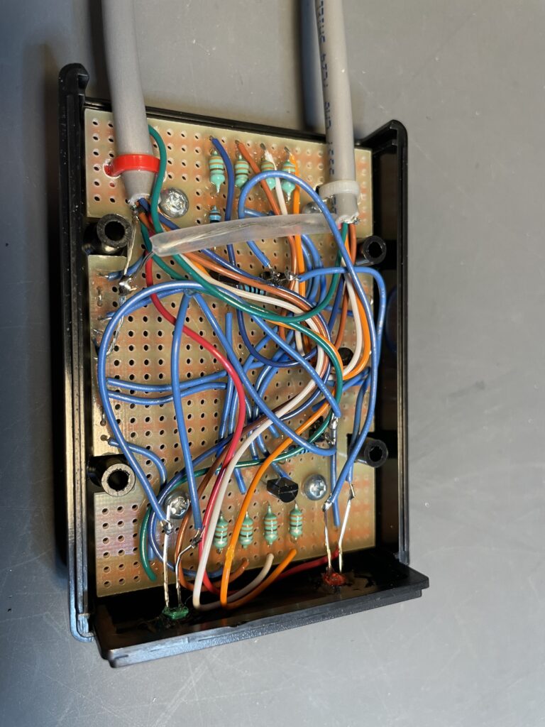
There it is fully wired and ready for the smoke test. A metal case would be better for shielding. Maybe for the next one but this would do for now. Also for the next one some RF bypass capacitors throughout the circuit would be a good addition.
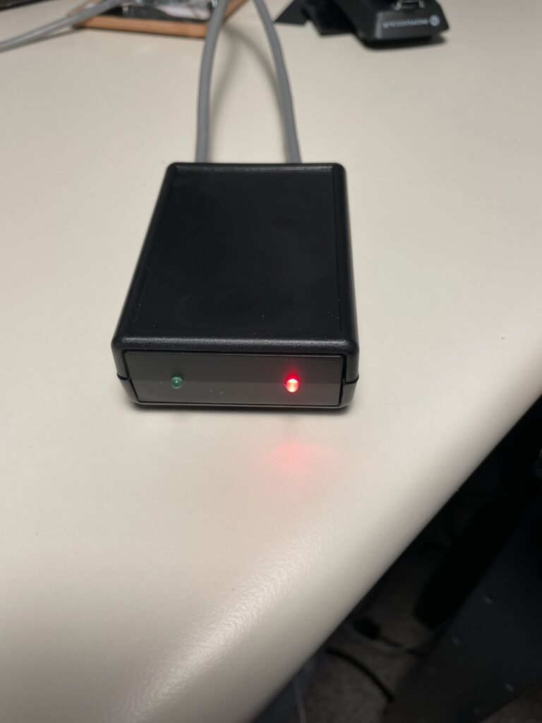
There it is done and on the air. The interface circuit can be used to connect virtually any commercial VHF or UHF radio to a CM108 sound card for use in an AllStarLink node. This was one of my goals.
Radio interface:
- PTT active low
- COR active low
- De-bounce of 100 ms on both PTT and COR
- +12 V DC power is supplied from the radio
- Tx audio connected directly to sound card
- Rx audio connected directly to sound card