I recently acquired a piece of test equipment that was lacking on my test bench. As I work on a lot of old radios and as old radios have capacitors that are either bad or suspected to be so a decent capacitor leakage tester that operates at the voltages found in old vacuum tube equipment would be very useful to have. I’ve been wanting one for a while.
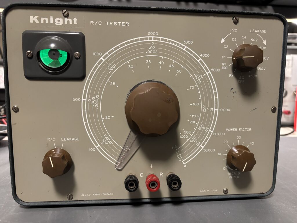
This Knight R/C tester was part of the gear retrieved from our recent trip to Medicine Hat where I picked up the RCA AR-88F. The little Knight was in quite good physical condition. Not perfect but more than good enough. The only real flaws were some marks on the front panel, as you can see in the photo below.
This is a multi-function unit. It would not only test capacitors for leakage but it is also an R/C bridge. I have a good L/C bridge and good multi-meters so those functions had no appeal to me. But a leakage tester? Now that was useful. And this one went up to 450V, which is perfect for the old radios I have.
I brought it to life and found that it worked! An excellent starting point! The 6E5 “Magic Eye” tube appeared to be in excellent working condition. In a piece of test equipment this is not surprising as it would have had very limited use on someone’s test bench. In a radio receiver that was on for many hours over many years this would not likely be the case.
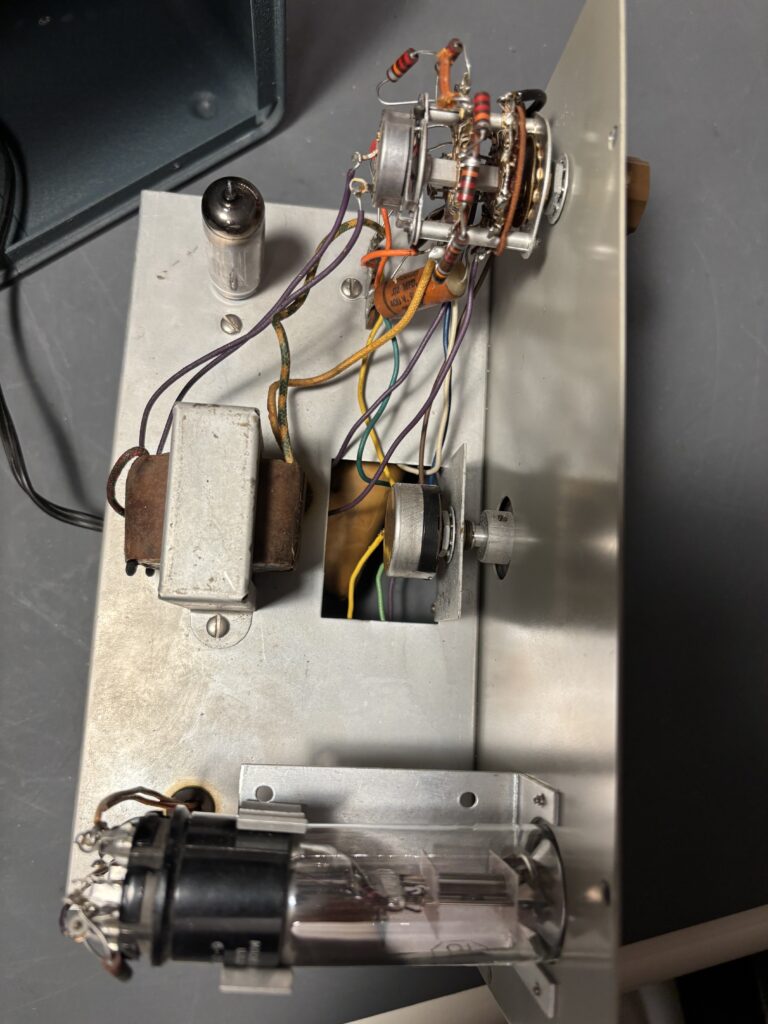
The interior was clean and nothing was amiss on the top side. Of course it would need the wafer switch contacts cleaned. Nothing was missing, scorched or modified.
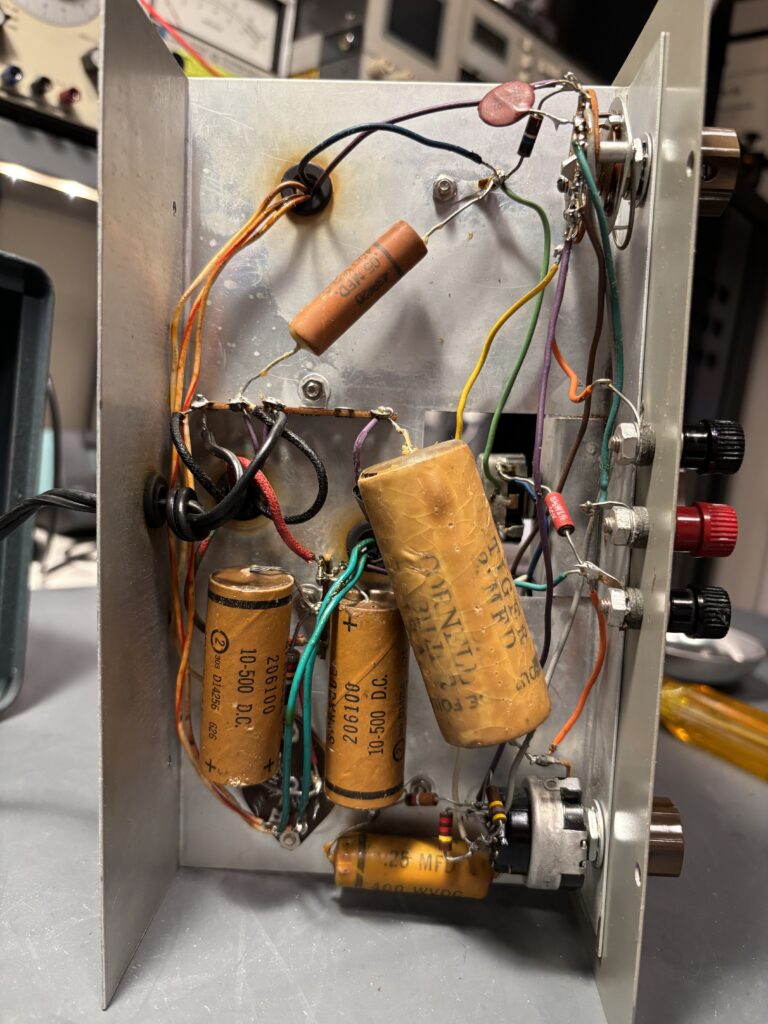
Knight equipment were kits made by Allied Radio. This one was well put together. Whoever did it did a very good job of it. The underside was also in very good shape. The paper capacitors would have to go, naturally.
The tubes, a 6X4 full-wave rectifier and the aforementioned 6E5 is properly called an electron ray indicator. RCA marketing called it a Magic Eye which I think is a damn stupid name but that’s what you get when you ask sales and marketing types for their opinions. Both tubes tested good on my basic little BK 606 DynaJet tube tester. Transformer voltages checked out and the power supply output voltages were good.
Meaning all this thing needed was six new capacitors and its’ wafer switches’ contacts cleaned. This was fun and easy work and once completed the little Knight RC tester worked like new!
Posted inUncategorized|Comments Off on Knight R/C tester
As $DAYJOB has me working in a P25 radio system I’ve been meaning for some time to get the OP25 software going and build a P25 scanner. And now that the Raspberry Pi has sufficient horsepower to handle this task I thought this would make a fun little project.
I had a couple of SDRs on hand that would work well and the combination of a Raspberry Pi and SDR could be dedicated to the task of P25 scanner in the ham shack. My first rendition was using a Raspberry Pi 4, my trusty old HackRF One and the “rx.py” receiver that is part of the OP25 package.
I got it working and won’t bore you with those details as this ended up not being the permanent solution to the p25 scanner problem. I needed the Raspberry Pi 4 elsewhere and OP25 can use more horsepower. So I acquired a Raspberry Pi 5. The older “rx.py” receiver has some shortcomings and was quickly replaced by the more modern and superior “multi_rx.py” receiver, also part of the OP25 package.
While the “rx.py” receiver was a great way to get started and learn with OP25 it has enough shortcomings that I don’t recommend it for anything beyond that: a learning tool and stepping stone to getting going with “multi_rx.py“.
As such I am going to skip right to the final state in this description and hope that it may be of some use to other folks wanting a P25 scanner.
The computer: Raspberry Pi 5
I bought a Raspberry Pi 5 with 8GB of ram, a case, a fan and a power supply. While 4GB of memory would have been more than sufficient, 8GB did not add a lot to the cost and it makes the device more usable for other tasks down the road should it be retired from P25 service and repurposed elsewhere.
The radio: HackRF One SDR
I had two SDRs already in hand. A HackRF One and an Airspy Mini. Either would do nicely for my purpose. I chose to start with the HackRF. I’ve been meaning to add a TCXO (temperature compensated crystal oscillator) to my HackRF so I performed that work as a prerequisite to this project using the TCXO from Nooelec for the HackRF. The on-board oscillator in the HackRF is pretty good but for ~$30 I would have something more stable which could only be helpful at ~800 MHz which is where our local P25 system lives.
The build
I downloaded the latest Raspberry Pi OS and got that up and running. A simple task and I won’t go into those details here. Now for OP25. This looked like it would take some time as documentation is not plentiful. Information about the project can be found here:
Then I found this very well-written how-to on getting started with OP25 and I used it, which saved me much time and effort. Many thanks to John, KN4FMV, for taking the time to write this up and for doing such an excellent job of it! It gave me a running start with OP25.
To get this going you will need to know some technical details about the P25 radio system that you intend to monitor. If you’re lucky it will be listed in the databases at Radio Reference. That will save you trying to figure out the the WACN, System ID, RFSS, NAC, control channel frequencies and talk groups.
Using John’s tutorial I now had a P25 scanner running using “rx.py” and monitoring the local site of our local P25 radio system. As I am in the middle of a big city and as the city is very well served with several P25 sites (in a simulcast configuration) I have no problem with received signal strength.
But I do live in a valley and the ham shack is in the basement so I decided that taking a feed from my television yagi would work very well for me, despite the facts that the antenna is for the wrong band and is pointing inthe wrong directionand the feed line impedance is 75 ohms. The mast-mounted LNA would more than make up for any deficiencies as it was a broadband unit that covered the 700 MHz public safety band. This ended working very will given that the P25 radio sites here in the city are very strong to begin with.
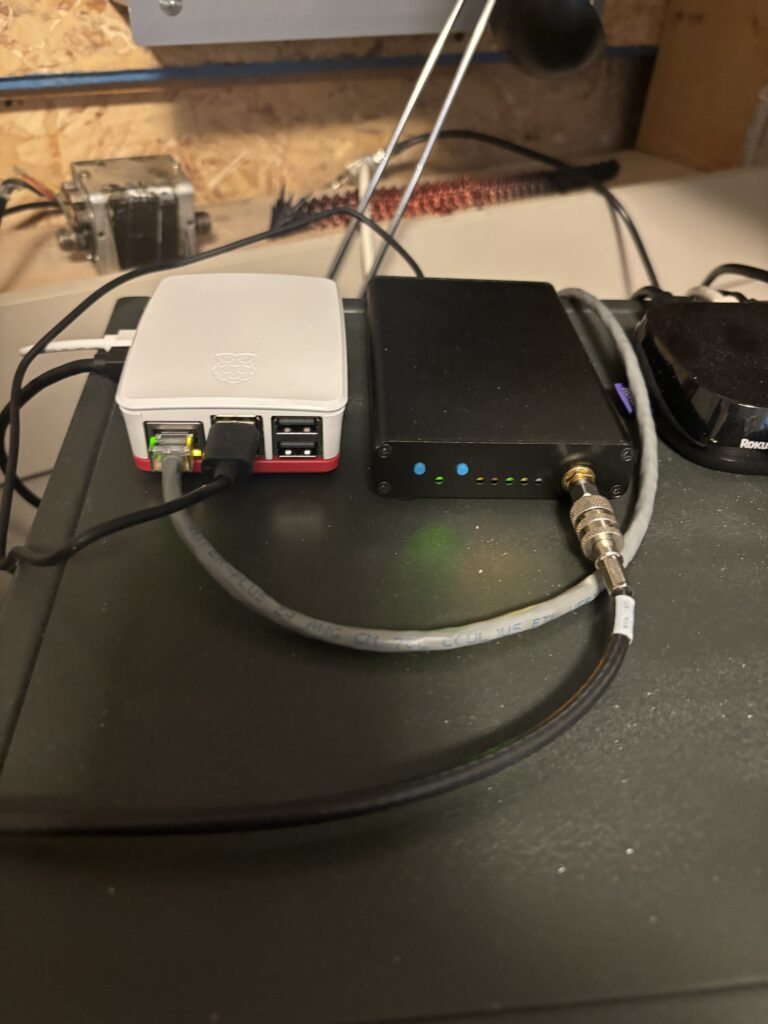
Here is the Raspberry Pi 5 (left) and HackRF (right) perched on top of my Hammarlund HQ-129X and working very well.
Now the fun would begin: multi_rx.py
After some time using the “rx.py” receiver its’ deficiencies became apparent. There were audio artifacts. The configuration lacked flexibility. There’s no config file, one just plunks everything onto the command like. There’s no facility to deal with a control channel that moves about, as ours here do. And there’s more.
The author has stated that the code in “multi_rx.py” is better at packet re-assembly and that its’ performance is better. And there is a very flexible configuration file. It also supports multiple SDRs so one can monitor multiple systems.
That was that. I needed to move to “multi_rx.py”. The challenge here was that there wasn’t much for documentation other than some sample config files. Using those as a starting point and coupled with what I already knew about P25 systems in general and ours in particular I set to work.
This took a good amount of time in experimenting. I was also slightly hobbled by my lack of in-depth knowledge of Linux. I am a BSD guy and have been since 1992 or so. I’ve picked up a few things about Linux over the years via casual exposure but was missing a few bits of knowledge as it pertained to this project, like managing the screaming horror of systemd, for one.
Without going into all the detail I will say that I developed a working .json file (much trial and error here!) from the examples provided with the OP25 distribution. I got the audio sub-system sorted out. I built a talk group file, thanks to the information provided at Radio Reference. The web interface is useful once you have your configuration sorted out.
This would be a good time to thank the local scanner community for their diligent efforts to document these things! To build my scanner I needed control channel and talk group info and it was all there.
It’s working well and I am pleased with the results.
Posted inUncategorized|Comments Off on P25 scanner using a Raspberry Pi and OP25
This post is the first part of who knows how many detailing the restoration to service of what is a very special radio to me, an RCA AR-88. The saga began in February of this year.
The goal is for completion of all work the end of September at the very latest. Ready for the winter radio season and ready to provide not just operating and listening pleasure but the visual and olfactory ambiance that can only come from an old vacuum tube radio in the ham shack.
Acquisition
In February 2025 my pal Neil, VE6TCK, became aware of some radio equipment from the estate of a Silent Key, Frank Smith, VE6EW in Medicine Hat, AB. It included an AR-88F that looked to be in very good physical condition. As Neil already had an AR-88F and a CR-91, he figured, rightly, that I would be interested in this AR-88F. I had an AR-88LF when I was young, before I was a ham. I foolishly sold it and I immediately regretted that decision then and for the following four decades.
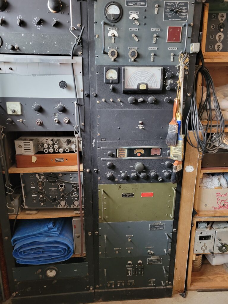
I’ve wanted another AR-88 ever since. Here was my chance to get one at a very reasonable price. The catch was that the widow wanted rid of both racks and all the gear in them, pictured below. To get that AR-88 we had to take it all away. As well, Medicine Hat is more than a five hour drive from Edmonton. So while the price was very attractive there was some additional time, expense and effort required. It was worth it as this radio is one of the special ones for me and this one was in good physical condition. Most of these are not.
Based merely on the photo below and a very brief description from a local ham a plan was formulated. When spring arrived, I, along with my XYL Donna and our friend Neil would make the journey to Medicine Hat and bring this equipment home. I wanted the AR-88F, Neil was interested in the Italian Geloso radio above it and we figured some of the other pieces may be of interest to others that we knew.
There it is as found in a garage in Medicine Hat, AB. The old ’88 looks good after sitting there for who know how many decades! The two racks pictured, along with all the equipment in them, had to go. This was our task that weekend.
We departed Edmonton on the Saturday and enjoyed a warm, sunny drive to the far southeast of Alberta, arriving around 1500h. That gave is enough time to get everything removed from the racks and the lot of it loaded up. We were not initially certain we would be able to accomplish everything on Saturday and were very pleased that we were able to do so! The next day we could eat breakfast and hit the road for home.
Inspection and evaluation
Back in my ham shack in Edmonton the initial inspection was good. The unit is complete and nothing was missing or damaged.
Some small modifications had been performed by some prior owner. Antenna connectors had been added on the rear apron: one BNC and one SO-239, but a good job was done on those. A chassis mount fuse holder has also been added and a proper job was made if that. This was all acceptable to me and would be left in place.
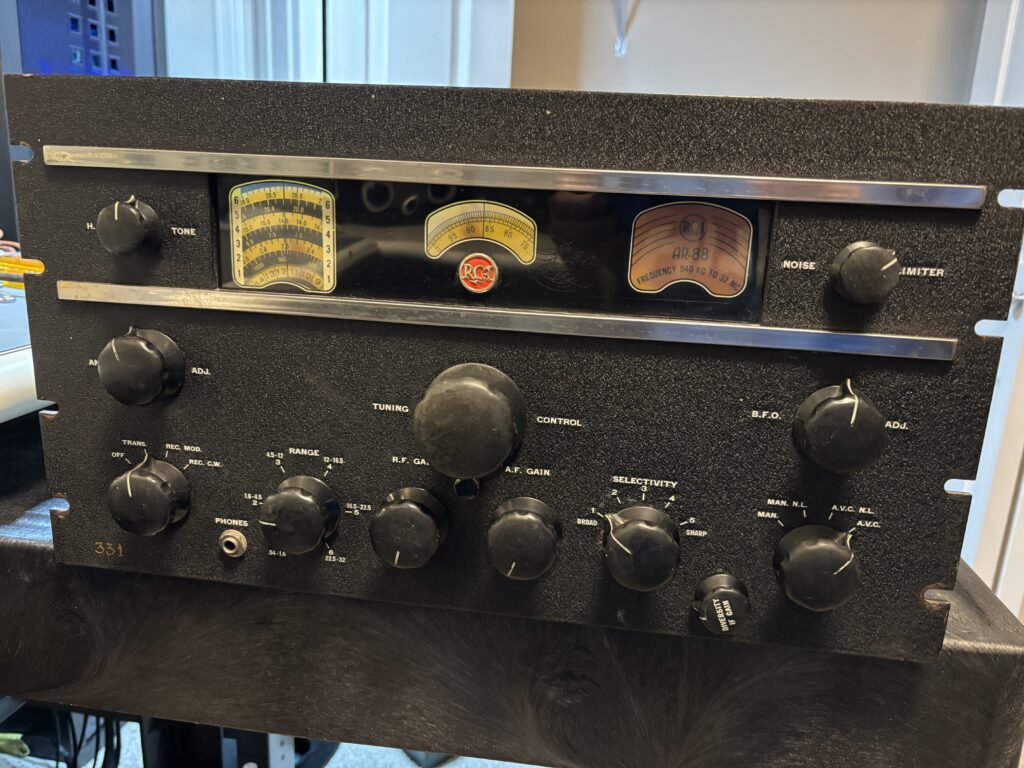
The front panel is in excellent condition. All knobs are the correct ones and in good condition. The dials and dial windows are in very good condition. All of that was very good news as I would only have to deal with electrical repairs, which is the fun part.
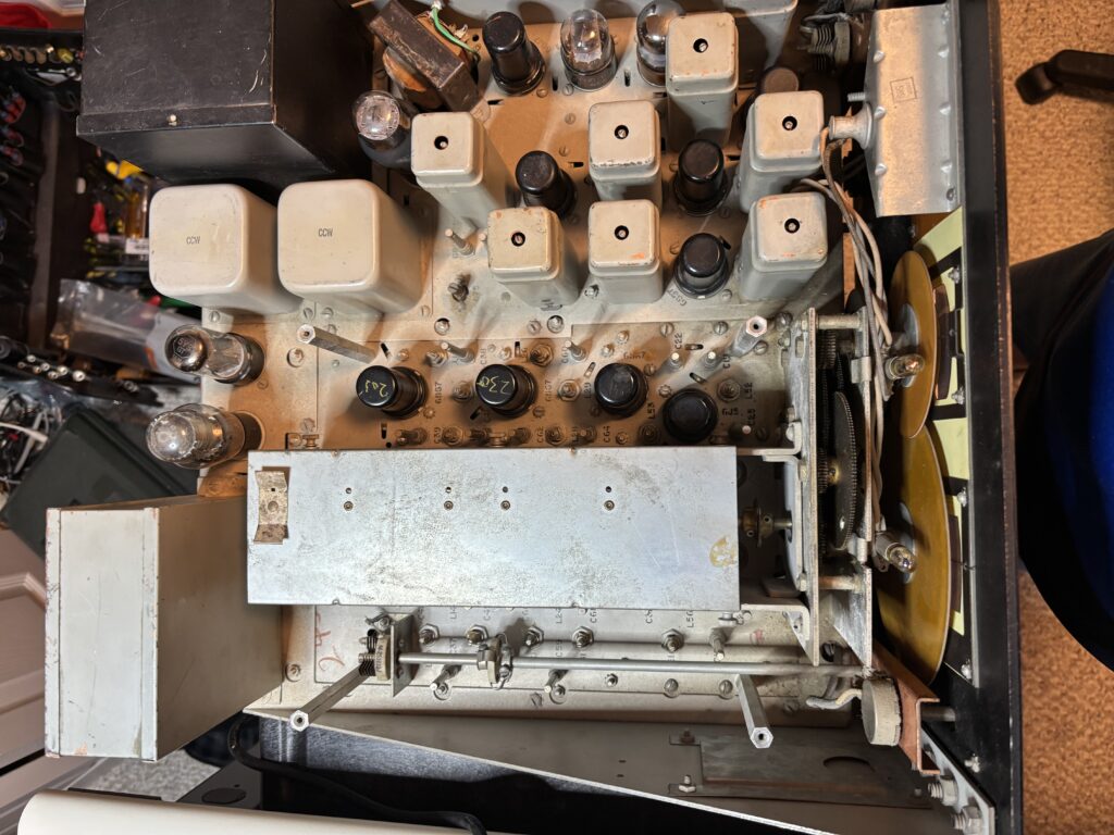
There’s the topside of the chassis with the RF shield removed to get at the tubes that live under it. All the tubes were removed, cleaned and tested. There was no leakage from the power supply inductors, power transformer or main filter capacitor(s).
The IF gain pot is missing it’s housing. The audio output transformer had been replaced at some point. It has only one secondary winding and I don’t yet know what impedance it is. I assume something low. That will need to be understood at some point.
Next up is disassembly. There will be a lot of screws, washers and nuts to keep track of. As I take things apart I put all the fastening hardware in plastic bags with a note in each one to remind me from whence it came. When reassembly time comes some weeks or months from now this will be invaluable.
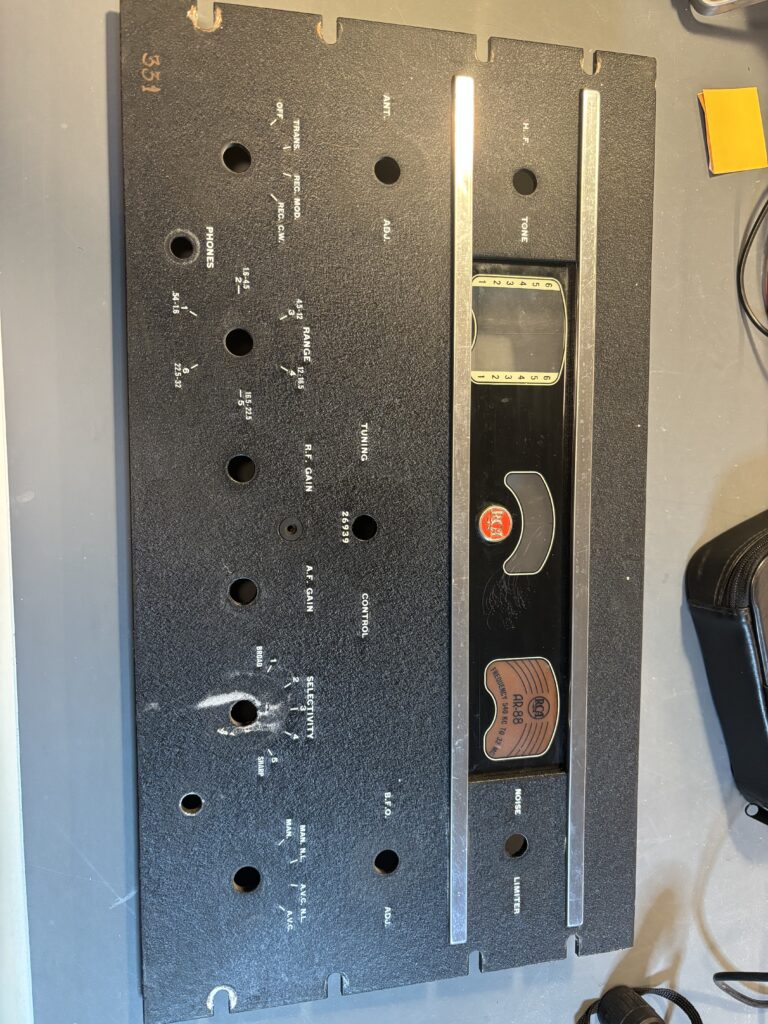
The knobs and front panel were removed first. The white material behind the “selectivity” knob was from the deteriorating felt spacer behind the knob. It wiped off with warm water.
Other than some dust everything under the front panel looks really good! The mechanical construction of these radios is excellent. Based on the condition of the dials I don’t think I will need to replace these but Radio Daze does make replacement dials if needed.
The two covers on the RF compartments underneath were then removed. How many decades has it been since anyone was inside these? Everything looks in excellent condition, even the wafer switch contacts are clean. They will still need a cleaning and some exercise to work properly again.
Before I went any further I needed to know if the radio worked at all. I eased it back to life on my Variac over a period of some hours. I was able to receive local AM BCB stations! The audio was extremely low but it wasn’t distorted. Switches were naturally fiddly. But RF went in and AF came out. Now I can begin the repair and restoration work!
Scope of work
The following tasks will be undertaken as part of this project:
replace all paper capacitors
replace all micamold capacitors
replace power supply filter capacitors if needed
replace all resistors that are out of tolerance
replace all vacuum tubes with NOS
clean gearbox
full IF and RF aligment
verification that the replacement AF output transformer is the proper type, replace if not
clean front panel, knobs, dials and windows, repair or replace as needed
replace dial lamps
clean chassis, front panel and knobs
I have the capacitors I need for this job. I still need to acquire some resistors and a full set of tubes.
Off we go… more to come as the project progresses…
Posted inUncategorized|Comments Off on RCA AR-88F – part 1: acquisition and evaluation
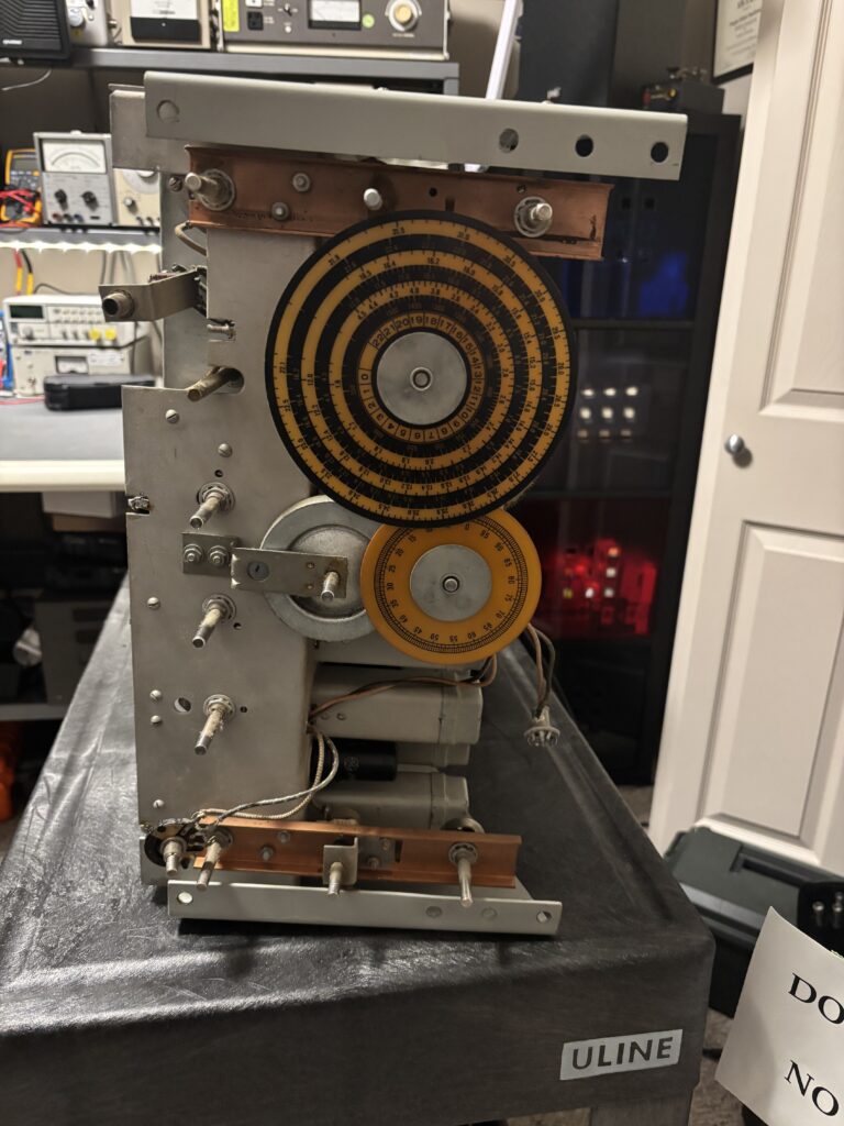
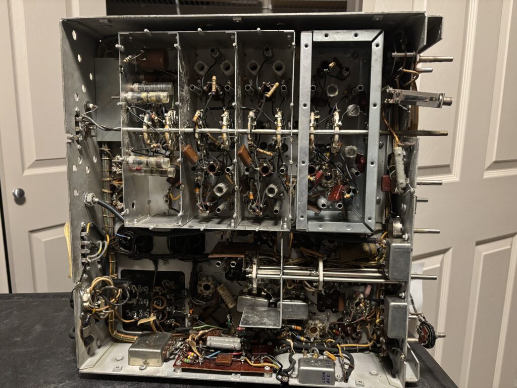
This next item is not just a piece of radio history, it is a piece of local radio history. Local being Edmonton, Alberta, Canada.
It’s a crystal oven for a broadcast transmitter. I don’t know what years it was in use but given the frequency of 930 kHz it is a virtual certainty that it was used at a local AM broadcast station, CJCA, which has operated on that frequency from 1935 to this day.
CJCA was, in fact, the very first radio station here in Edmonton starting in 1922. And there is a personal connection for me as my grandmother Hazel worked for them in 1922 (they were on another frequency then) when they were starting up operations in an unheated shack on the roof of the Edmonton Journal building in downtown Edmonton where she worked as a stenographer.
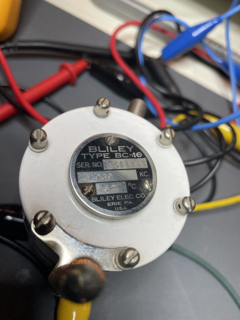
I picked this unit up at an estate sale of a long term and avid collector of vintage radio equipment. It’s in perfect condition. It was made by Bliley Electric Company of Erie, PA and bears a model number of BC-46 on the metal plate on the top and BC-46T on the label affixed to the side of the unit.
Here’s a picture of the top plate showing the frequency of the crystal inside and the specified oven temperature of 52C.
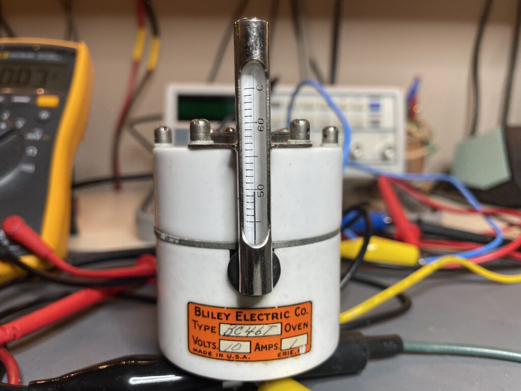
The next picture shows the front of the unit where you can see the thermometer showing the oven temperature and a label indicating the oven power supply specifications of 10V @ 1A.
When I stumbled across this device and noted the frequency I knew that I should acquire it and preserve a piece of local radio history. I was curious to find out if it still worked and the first step was verifying that the oven still worked.
I hooked it up to my trusty HP power supply and dialed up 10V DC. I noted that the unit was drawing 900 mA of current. After a few minutes the mercury in the old thermometer (and it’s silver, not red, so that may help to date this thing) started to rise and the ceramic housing felt warm to the touch! Several minutes later it was sitting at 50C.
There’s the test set up. Amps on the left meter and volts on the right. I noted that the temperature rose to 50C and then the thermostatic control circuitry inside this little gem kicked in. I observed the heater cycling on and off to maintain that temperature. The first functional test had passed!
The unit has a base that plugs into the old five pin tube sockets. The same type used by the 807 triode and others. At some point I shall have to build a test platform for it. I am envisioning a small metal box with an oscillator circuit, terminals for external power and RF out with a socket on top to plug the module into. If and when I do that I will document it here.
When I was a young boy in the 1960’s my grandmother always had CJCA on her Simpsons-Sears table top vacuum tube radio on her kitchen table. I ate many meals at that table with CJCA tuned in and warm audio coming out of the old radio. As an adult I listened to CJCA after they switched to a talk radio format. In the mid-1990’s they switched to broadcasting religious rubbish and they are no longer fit to listen to.
But there was a time when CJCA was the king of the AM airwaves here in our good city and so I shall keep and preserve this device. I love the old technology and also the cutting edge. It’s all wonderful stuff!
Posted inUncategorized|Comments Off on Bliley BC-46 crystal oven
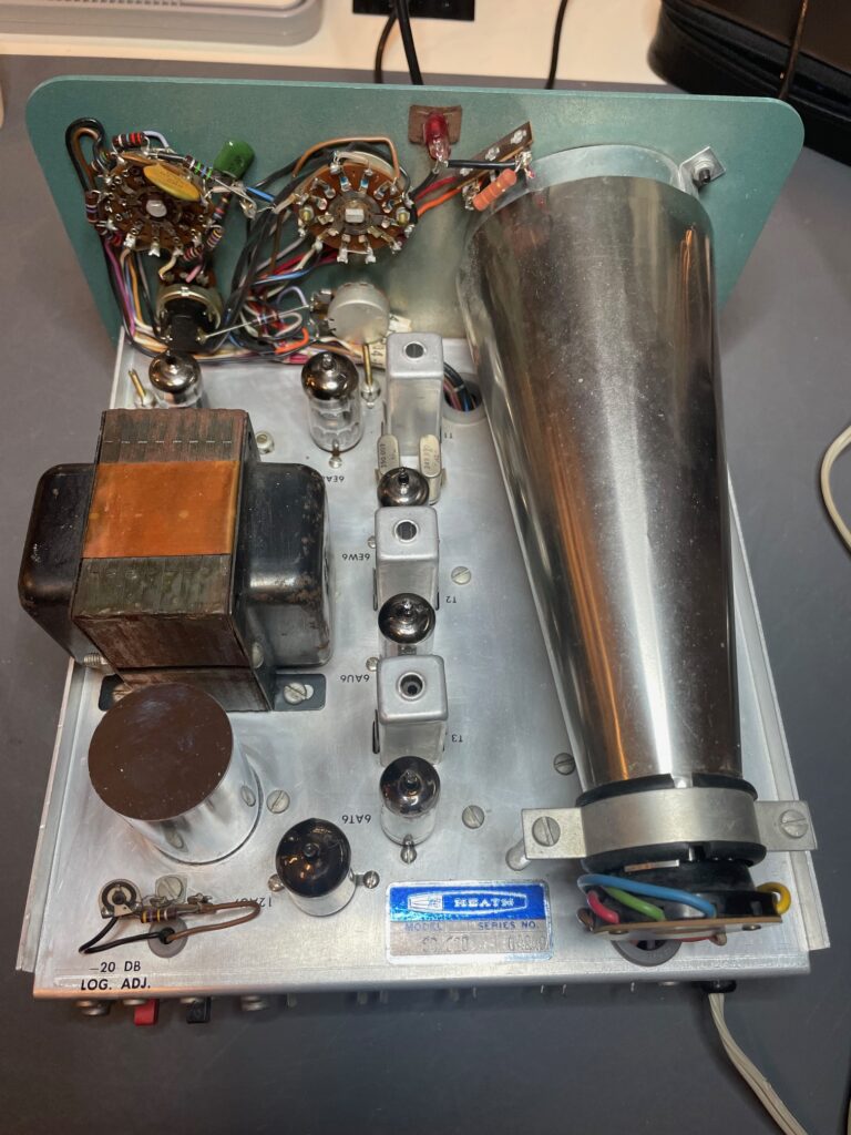
Last year I acquired a very nice Heathkit SB-620. It was complete, clean and very good cosmetically. I thought that it would make a fun addition to use with my vintage receivers so I undertook the project of getting it working properly. Here is the how the interior looked when I received it (other than the big electrolytic capacitor that I replaced before taking this photo):
These units are basically a narrow bandwidth spectrum analyzer designed to take a feed from the IF of a receiver and display a pass-band of a width selected via the controls. When the kit was assembled the user would choose the frequency of the IF to be used. The frequency chosen affects a number of different components in the circuitry. Heathkit provided all the components needed for a wide variety of Intermediate Frequencies and the builder would use the ones needed. The rest could be put into the old junk box.
The unit I purchased was built for an IF of 3395 kHz which was used by Heathkit equipment of the era as well as some other receiver manufacturers. As I intended to use this unit with my Collins 51S-1 oy maybe my Collins R-390A I’d have to do something about the incompatible Intermediate Frequency. But that was a problem for later.
Right now the goal was to get the unit into proper working condition. To that end I ordered a capacitor kit from Hayseed Hamfest and added the optional resistor kit. That seemed prudent given the small additional cost and give that 60 year old carbon resistors could easily be out of tolerance.
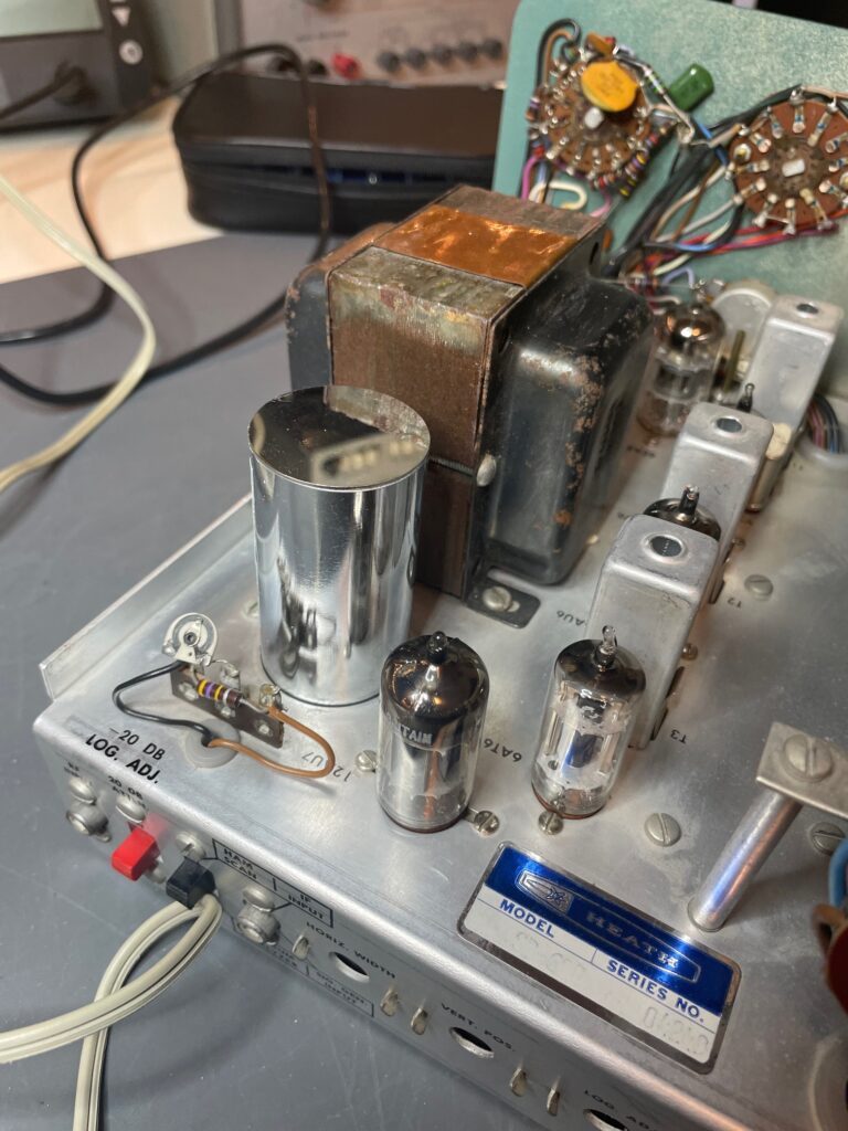
While I awaited the arrival of said kit I checked the tubes and replaced any that were suspect. Then I gave the wafer switches a good cleaning with DeoxIT and MG Chemicals Nu-Trol contact cleaner. Bringing the little unit up on a Variac showed that there was a nice trace on the CRT and the CRT itself looked to be in excellent condition. Based on that and the excellent condition of the face and cabinet it appears that this unit had seen not a lot of use and had led a soft life in someone’s ham shack somewhere.
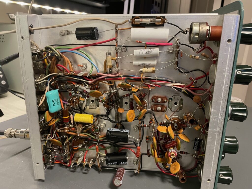
Once the capacitor/resistor kit arrived I set about replacing all those components. This was a relatively straightforward and enjoyable endeavour. Who doesn’t enjoy the smell of a hot soldering iron and flux vapour in the shack, punctuated by the occasional “thwap!” of the ol’ Soldapullt?
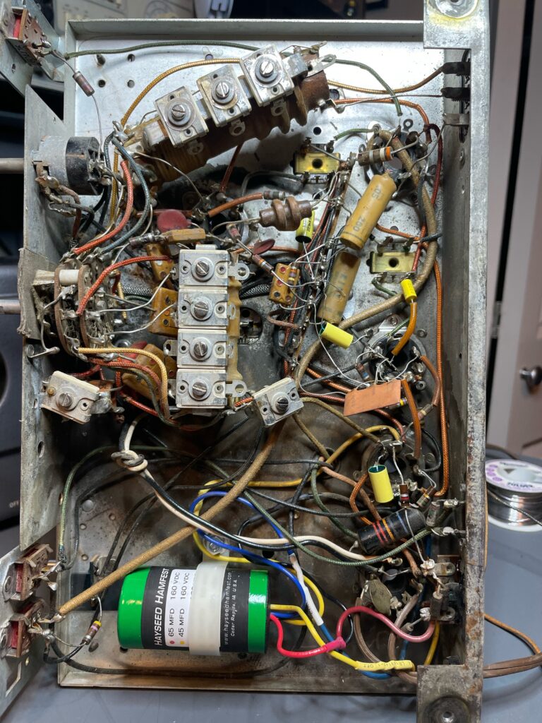
There’s the underside of the chassis after the capacitor and resistors had been replaced:
Here you can see the nice chrome-plated multi-section capacitor can provided by Hayseed Hamfest. The can contains four electrolytic capacitors in this unit.
Once the new R’s and C’s were installed and an initial smoke test showed no problems and a nice display it was time for the alignment process. The manual offers two methods for this, one with test equipment and one without. As I am fortunate enough to have good test equipment I used that method.
As this little spectrum analyzer is basically a super-heterodyne receiver the alignment process is similar. I normally do two passes through the alignment process to get it spot on but I just did one in this case as I may end up modifying it for a different IF anyway. I just wanted to make sure it was working properly and it seems to be.
I am pleased with the result and now I need to figure out how I will get it hooked up to the 51S-1 which has an IF 0f 500 kHz. The 51S-1 does have an “IF out” jack on the rear apron so that part is solved.
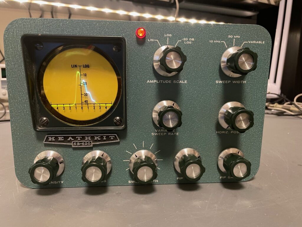
Here is mine running during the alignment process.
The cabinet, knobs and yellow display filter are all in excellent condition. The SB-620 is not nearly as common as it’s transmitter mate, the SB-610, is so I was lucky to get one and in such good condition.
The CRT is a 3Rp7 which is no longer available and uses a high-persistence phosphor to compensate for the slow scan rate of the beam. I was doubly grateful that the CRT was in excellent shape! While a substitute could likely be found it would not be the high-persistence 3RP7 that is really needed for proper use of this machine.
The P7 phosphor gives the high persistence display needed for spectrum analyzers and radar displays. P7 has two colors giving two different persistences: there is a short-to-medium one via purple-blue fluorescence and a long one via yellow-green phosphorescence. By using a color filter after the screen either color, and therefore either persistence, can be selected. In the case of the SB-620 they wanted to use the longer persistence and so you have a yellow filter in front of the CRT.
There are also two NE-83 neon lamps used in the circuitry. One you can see on the front panel. But it is more than a power indicator. It’s main use is actually as a voltage regulator for the local oscillator. The other NE-83 can be seen on the underside of the chassis. It is part of the relaxation oscillator circuit in the horizontal sweep section. Because neon lamps degrade over time and because they perform important functions in this unit I’d like to replace them. That is also on the to-do list for the rejuvenation of this fine little Heatkhit Scanalyzer.
More to come on this project as it progresses.
Posted inUncategorized|Comments Off on Heathkit SB-620 “Scanalyzer”
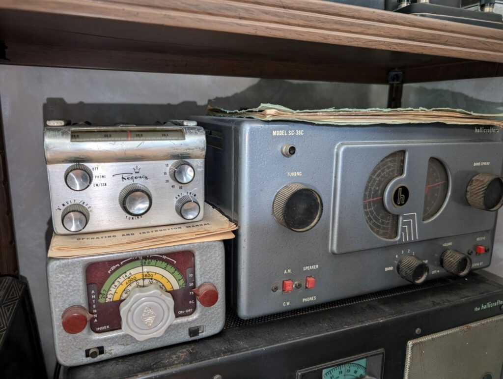
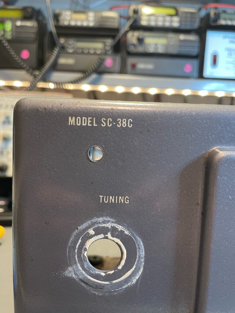
I recently attended a sale of equipment from the estate of a local ham, Sig Preuss, VE6SP. At the sale I picked up a Hallicrafters SC-38C that was in decent condition cosmetically and that was complete. No, that is not a typo in the model number. More on that later. It’s a very interesting story!
There was also an S-38 offered at the sale. I asked my XYL which one she preferred the looks of as it was my intent that this stylish little radio would go in the living room so we would have a radio on the main floor of our home to listen to the news on. She preferred the look of Hammertone finish on the SC-38C to the black of the S-38. So that’s the one that came home with us.
On the right is the SC-38C as found when purchased. Note the hacked-in RCA jack.
I eased the little Halli slowly back to life on my Variac and found that it did indeed work, which was a great start to the project! Naturally it had some problems, as could only be expected in a 70 year old radio. It was not very sensitive and the audio quality was poor.
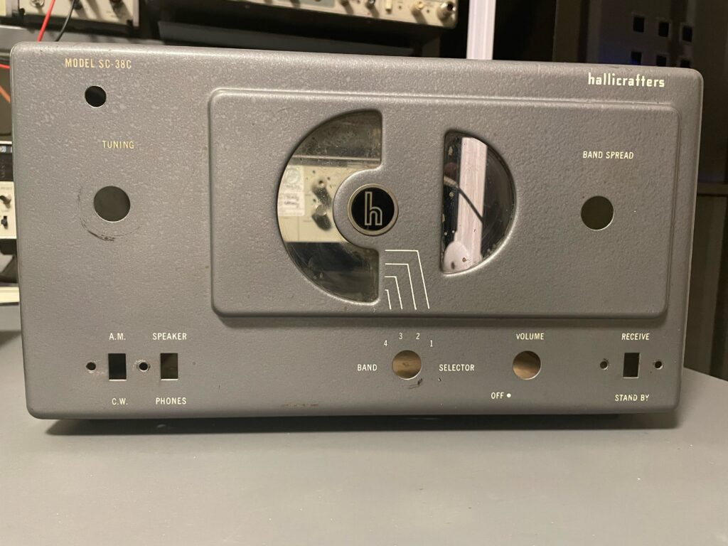
The case was not in bad shape. There was no damage to it, just some small scuffs and scratches here and there, nothing of significance. While not perfect it was certainly good enough. My XYL liked the patina and originality of the radio and didn’t feel that it should be re-finished. I agreed with her. The knobs were filthy but undamaged. The dial windows were dis-coloured and no longer clear. All things that were readily fixable.
The worst thing, for me, was that a prior owner had drilled a 1/4″ hole in the front panel, below the model number, and installed an RCA jack which was wired to the headphone connector on the rear apron using #18 bell wire. That give a clue as to when it was done. Perhaps 1960’s or 1970’s? Something would have to be done about that and I had an idea. The good news was that whoever did it had chosen a good location and centered it under the model number. This turned out to be fortuitous.
The empty case before cleaning and with original dial windows.
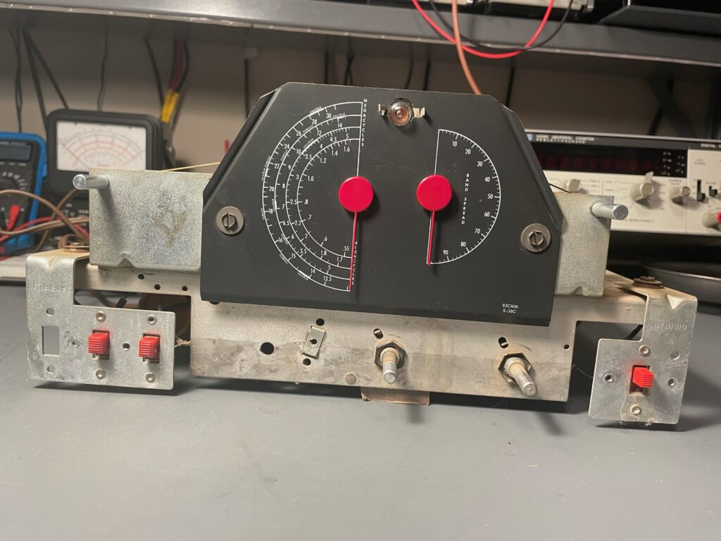
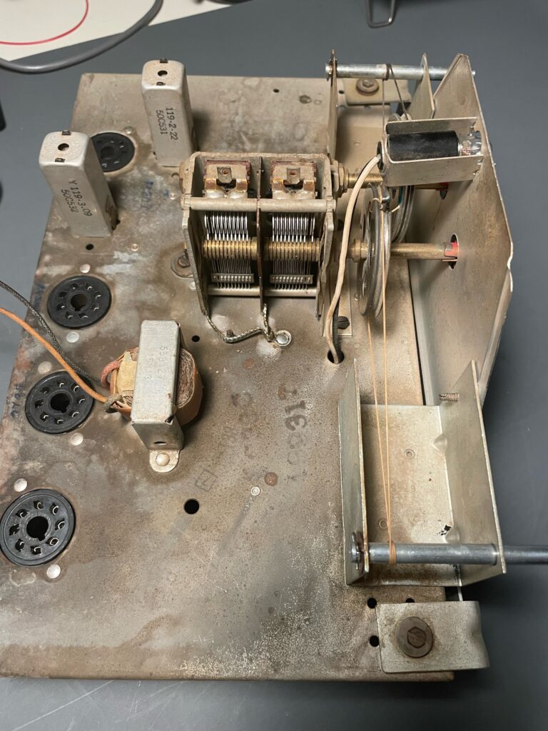
I pulled the knobs and set them soaking in hot, soapy water. The radio was taken out of the case for a full inspection. This revealed that one tube was the wrong type (12SH7 in place of 12SG7 IF amp), the chassis was naturally dirty including the plates of the main tuning cap, the dial lamp was out and all the original wax/paper capacitors were still in place, as was the multi-section electrolytic in the power supply. The main tuning dial cord was also broken.
On the test bench.
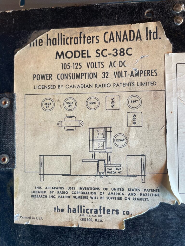
A fascinating detail that had gone unnoticed now came to light. The bottom cover had the usual Hallicrafters labels affixed to it. They were worn but perfectly legible. The main label, however, held a surprise. It said two things of interest. One, it said “the hallicrafters CANADA ltd” and the other was “MODEL SC-38C“. This radio was built in Canada and was given a model number that reflected that! Who knew? Certainly not I.
Also, on the top left corner of the front panel where it would normally say “S-38C” it said “SC-38C”. On the top right of the front panel it said just “hallicrafters” rather than “the hallicrafters co.” as US-made radios did.
The labels on the bottom of the radio show it as a Canadian-built model.This a Canadian made Hallicrafters, model SC-38C
This was a new and interesting facet of Hallicrafters history to me. Some searching revealed that Hallicrafters had opened a factory in Don Mills, ON in 1954. In 1955 they sold it. As the S-38C was made from 1953 to 1955 then my SC-38C was made in either 1954 or 1955. I can find no reference anywhere to the SC-38C but I did find references to the SC-40B and the SC-77A which were the Canadian variants of the S-40B and S-77A respectively. They would have also been built in the Hallicrafters Canada factory in Don Mills, ON. Interesting Canadian radio history, to be sure.
If you are reading this and you have any knowledge of Hallicrafters in Canada, their Canadian-made radios or anything related, please shoot me a message. My email is good at QRZ.com
The inspection being complete a plan was thus formed. I ordered a re-cap kit from Hayseed Hamfest http://hayseedhamfest.com and new dial windows from Retro Radio Repair http://dialcover.com. Tubes were tested and weak ones identifed. The 50L6 AF output amp was shot. The 12SG7 IF amp had the wrong tube in it’s socket, a 12SH7. The 12SQ7 AF amp/detector/AVC was weak as was the 12SA7 converter. Only the 35Z5 half-wave rectifier was healthy.
The main tuning dial cord has been re-strung and the main tuning cap has been cleaned.
Good tubes were sourced (thanks to my pal Neil, VE6TCK/VE6JW) and while I waited for the caps and dial windows to arrive I started the cleanup. The main tuning cap plates were very dusty so those were cleaned. A basic chassis cleaning was done. The dial cord was re-strung, a mercifully simple path on this little radio! Thanks again to Neil who provided a length of the right dial cord. The lone dial lamp was replaced (#47). The knobs were pulled from their soapy bath and given a good scrubbing with a nylon brush and put back into another hot, soapy bath for round two. They were not quite clean enough yet.
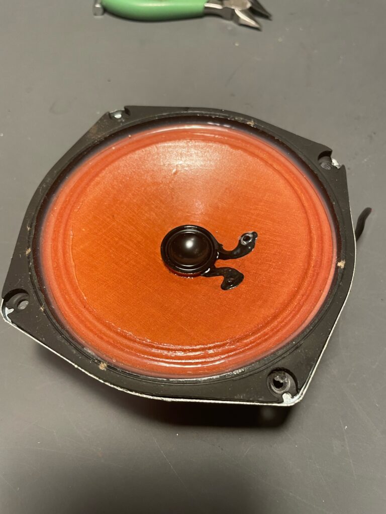
Next the old dial windows and speaker were removed and the case was cleaned inside and out. The original speaker had to go. The problem there was that the spacing of the mounting studs was not compatible with anything I could find off the shelf. After some days spent searching for a compatible speaker, and half in desperation, I disassembled a Harris mobile speaker I had as it looked like it might be close. And it was!
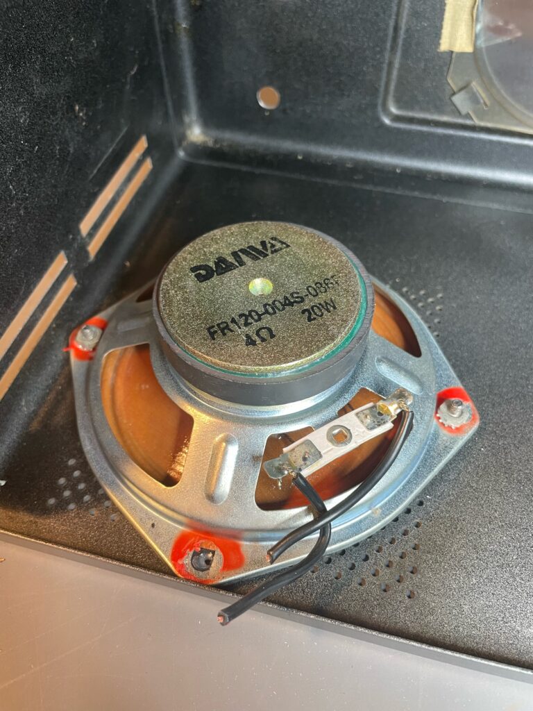
The stud spacing was tight but it fit. All that was needed was to tweak one of the corners of the speaker with my Klein Grips so that it didn’t interfere with the top lip of the case. The Harris speaker was even the right impedance. Hallicrafters specified a 3.2 ohm speaker and this one was 4 ohms. I’d always like the sound of these speakers with my VHF/UHF mobile radios so I knew it would sound good in the little Halli.
The new speaker. A Daiwa unit with a nice, big magnet!The new speaker installed in the case. It needed a tweak to fit properly.
Now I needed to do something about the 1/4″ hole in the front panel. My pal Neil came to the rescue, yet again, with a vintage 5/16″ neon panel lamp that absolutely looked the part for a radio of this vintage. It had a nice red lens and all I had to do was enlarge the 1/4″ hole to 5/16″ to install it. This was a good thing anyway because whoever drilled the 1/4″ hole left a bunch of burrs on the inside of the case. Sloppy work, that.
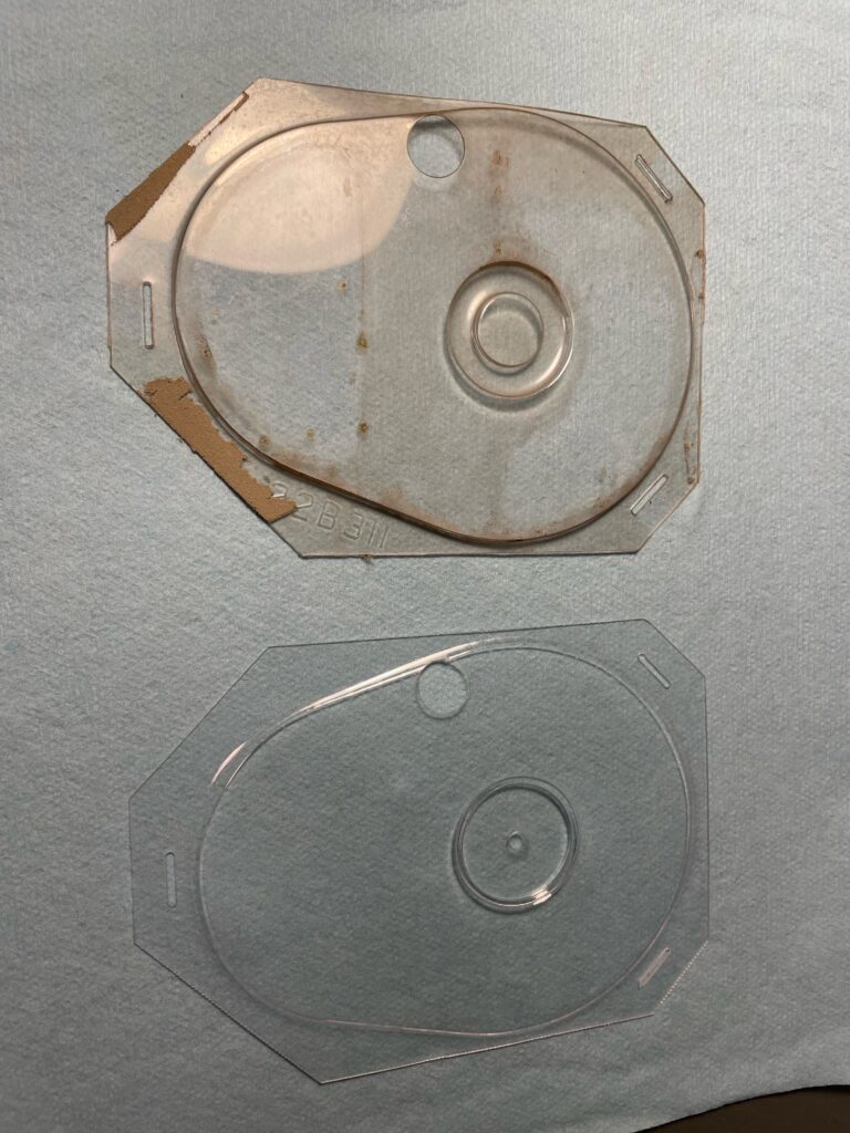
The dial windows and capacitor kit arrived so now it was time for the electronics work. The dial windows were a perfect fit and reasonably priced, too. And what a difference they made to the appearance of the little radio! Next up was the capacitors. I always do the power supply electrolytics first and then fire the radio up and see how it is.
There were then six paper/wax caps to replace so I did two at a time and fired the radio up between rounds to ensure I hadn’t make any mistakes and to see what improvement there was. The big improvement, to my ear, came from the capacitor that coupled the detector to the AF amp. It was likely leaking some of the B+ from the detector anode into the grid of the AF amp.
The old and the new dial windows.The underside of the chassis with some of the capacitors having been replaced. Two left!
Once all the capacitors were in place I considered the state of the three slide switches. Those things were cheap when they were new and they never age well. As I was never going to change them from their default positions I hard-wired them into that state. I didn’t want any high-resistance connections in those parts of the circuit. I also installed a polarized two-wire power plug. As this radio has no power transformer one side of the line is connected to the chassis at all times. I made sure that was the neutral side.
Now it was time for the alignment. For this I use my trusted HP 8657A signal generator as the signal source and my Simpson 260 VOM to measure the output. An analog meter is the only way to go when peaking levels.
It’s a very simple radio and the alignment procedure reflects that. When I align a radio I always do it twice. Once to become familiar with the process and once more to get it just right. Amazingly, the dial calibration was very close from the start. The signals did peak up very nicely as I went through the alignment. Octal tubes don’t do well above 20 MHz and the SC-38C is pretty deaf on the high band, as expected.
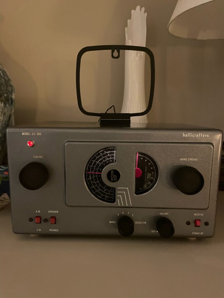
I put the chassis back in the case, installed the knobs, wired up the speaker and new old power indicator and hooked up a loop antenna I had from an old stereo receiver we had. Unlike other five tube sets the little Halli has no internal antenna. The final bench test after re-assembly was a success.
Once in it’s new home in the alcove above our fireplace the little radio looked good and sounded even better. The power indicator that shouldn’t be there actually looks like it belongs there with its’ soft red glow. The #47 dial lamp is dim, as they are, and the whole package just looks “right’. I am very pleased with how it came out and I couldn’t have done it without the help of my pal Neil.
The wee Halli In it’s new home.
I chose the S-38 series specifically because they are small and very stylish. These were the first radios that famed industrial designer Raymond Loewy designed for Hallicrafters. He went on to do more work for The Hallicrafters Co. They are a very simple design and work amazingly well for what they are. There is beauty in simplicity.
Using the little loop antenna here in the North Saskatchewan River valley in central Edmonton the local AM BCB stations are loud and clear and you can tell that the AVC is working well: 580 CHAH, 630 CHED, 740 CBX, 880 CHQT and 930 CJCA.
840 CFCW in Camrose is not as strong as the local stations but it is clear. 1440 CKJR in Wetaskiwin, which is 10kW compared to 50kW for all the others, is weak and noisy but can be received. That was during the daytime.
I am looking forward to hear what winter nights bring!
Posted inUncategorized|Comments Off on Hallicrafters SC-38C (not a typo!)
When I first built my AllStarLink node I had the choice of using the original AllStarLink software or the newer and more advanced HamVOIP software. At the time I chose to go with HamVOIP.
This was not an easy choice to make because despite HamVOIP being “newer and better” than ASL, the source code was being withheld by the developers. This was in clear violation of the terms of the GPL (the GNU General Public Licenses).
There’s a good amount of discussion available on this subject all over the place so I won’t bore you with it here. I will say that I have a low opinion of those in charge at HamVOIP.
I was therefore extremely pleased when the folks at AllStarLink recently released a new version of their software. The improvements are vast. Goodbye, HamVOIP. Hello AllStarLink v3.
I would recommend that all HamVOIP users make the switch. You will be happy that you did.
I also moved my AllStarLink node from my Raspberry Pi 4B to a Pi 3B. I wanted the Pi 4 for the DMR node and the Pi 3 was plenty powerful for the AllStarLink node. The Pi 3 fan is a 5V job but I run it at 3.3V so that it’s quiet enough to live in the ham shack and not be a bother while still maintaining an excellent CPU temperature of 42C.
Posted inUncategorized|Comments Off on AllStarLink node update
I had constructed my MMDVM DMR hot-spot using a Raspberry Pi 3 because the received wisdon was that putting the MMDVM hat on a Raspberry Pi 4 would cause it to overheat. My problem was that I found the web interface to be a little slow for my liking. It was usable, I just would rather it were more responsive.
So I set out on a search to find a way to use the MMVDM hat on a Raspberry Pi 4 and provide proper cooling. The solution was found in the Argon Fan Hat. The key feature that allowed this fan hat to work was that it passed the GPIO connector through to allow for the MMDVM hat to sit on top of it.
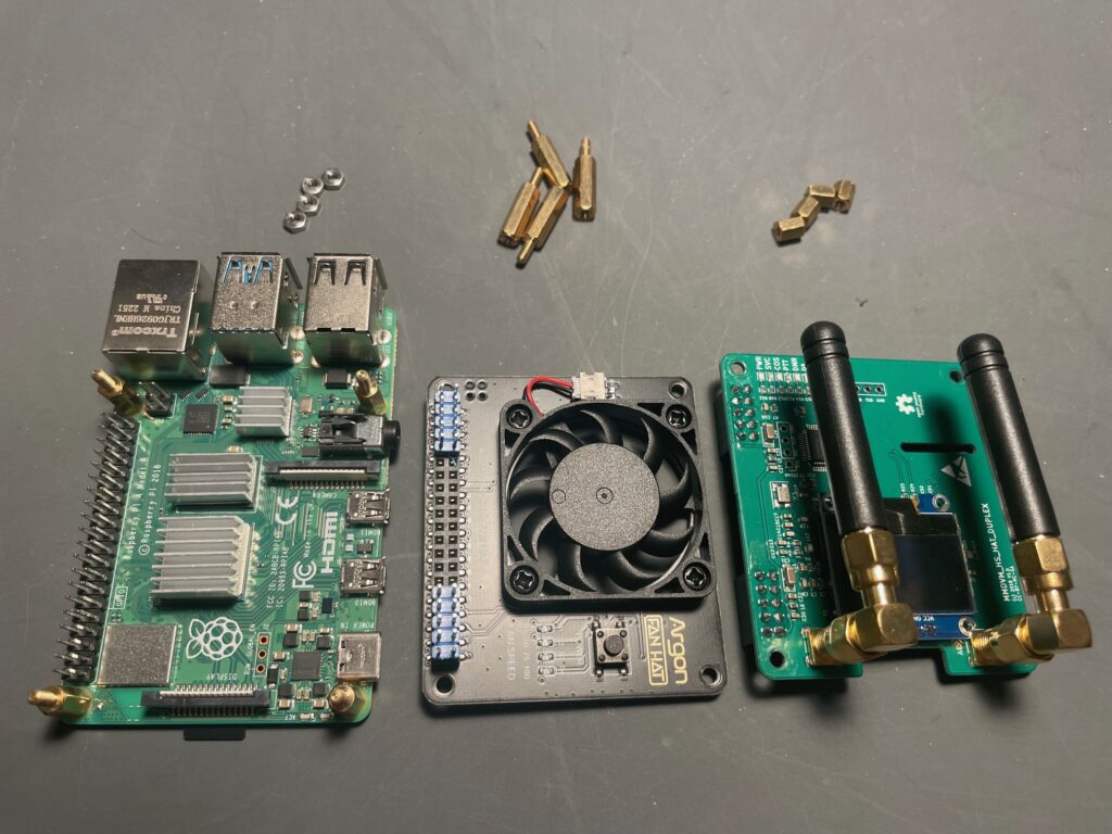
That, coupled with a Raspberry Pi stand-off salad allowed me to make a triple-decker sandwich. Left to right in the picture below we have:
Raspberry Pi 4B
Argon fan hat (plugs into GPIO header and passes it through to the next layer above)
MMDVM dual hat (plugs into the GPIO header passed through the Argon fan hat)
By using a Raspberry Pi hardware salad and selecting the right combinations nuts and stand-offs between the sandwich layers it all went together nicely. One thing to watch out for if you do this: I had to remove one of the bolts and nuts that attach the fan to the fan hat PCB. this was because it interfered with the CPU heat sink on the Raspberry Pi and wanted to unseat it.
The fan installs some software packages to do it’s thing. They don’t seem to conflict with any of the WPSD software packages that run the hot-spot. There is a configuration utility that allows you to configure the fan behaviour from on all the time to various speeds at various CPU temperatures.
Testing is in progress but initial impressions are good. The WPSD web interface is much more responsive using the Raspberry Pi 4B than it was on the 3B. I have the Argon fan set to run at 30% speed all of the time and it is maintaining a CPU temperature of 35C which is excellent.
While the fan is not overly noisy at 30% speed, my intolerance of fan noise in the ham shack means that my DMR hot-spot has been relocated to my Harry Potter data centre under the stairs along with the rest of the IT infrastructure.
I am very pleased with the overall results of this configuration.
Posted inUncategorized|Comments Off on DMR hot spot – version 2
I’ve been fooling around with DMR for a few years now and figured it was time to build a DMR hot-spot. I had a few DMR radios on hand already. Some Motorola XPR handheld radios in both VHF and UHF trim and also a TYT MD-380 for 70cm. But what really pushed me to do this was my desire to experiment on the 33cm band and the availability of the Retevis RT10 which is a 33cm radio that does DMR. And the fact that many of the MMDVM boards support 33cm.
First I acquired an RT10. Now I needed to make a DMR hot-spot. I learned that the Raspberry Pi 4B had issues with heat when coupled with an MMDVM hat and no fan so I picked up a Raspberry Pi 3B kit as the base for this project. With it’s lower clock speed and reduced heat output it was said to work good with a “hat” on it and no fan. Fans piss me off. The only noise in my ham shack should be coming from the speakers in my radios!
Next I grabbed an MMDVM “hat” (from Amazon) that plugs into the Raspberry Pi ‘s GPIO header. I chose a duplex one with a display just to keep my options open. For the difference in price it seemed silly not to. The one I got had a TCXO (temperature controlled crystal oscillator) so that eliminated the need to tune the offsets. I got lucky in that regard but given what I know now I would never even consider getting an MMDVM that didn’t have a TCXO.
For an operating environment I selected the WPSD software. It appeared to be the best choice at this time.
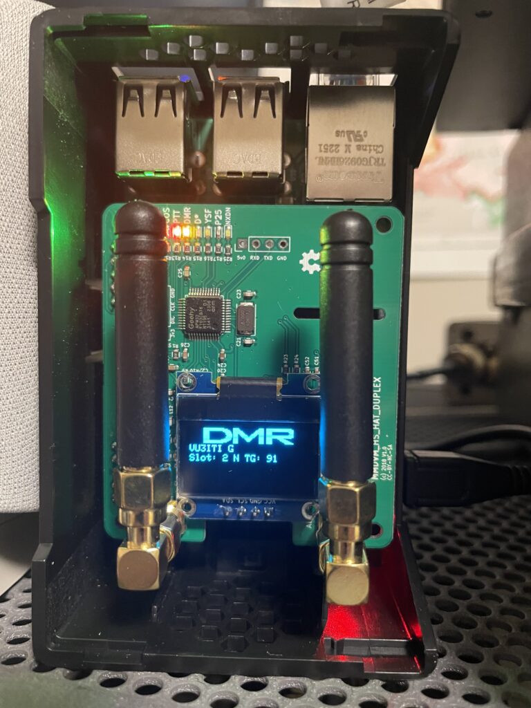
It all went together quickly and easily. Because I was already familiar with DMR and all that it entails I had little trouble getting it all set up. I joined my hot-spot to the Brandmeister network for my initial testing and usage. There are others but Brandmeister looked like the big dog on the block and a good place to start.
Experimentation with my DMR hot-spot continues. Once it was tested with the Retevis RT10 on 33cm I set it up for 70cm use with my old TYT MD-380, which also worked well. The MD-380 is a better radio that the RT10 in many ways but the point of my experiment was to use 33cm for something. And now I am.
Talk group 91, the worldwide talk group on the Brandmeister network, is quite active and always entertaining. Perhaps we will cross paths there.
Here’s a picture of the completed hot-spot in action:
Posted inUncategorized|Comments Off on DMR hot spot – version 1
A couple of my friends have been experimenting with AllStarLink and it looked interesting to me so I thought I would join in the fun. I’ve never had a Raspberry Pi and this gave me a reason to get one.
My plan was to build a simplex AllStarLink node for use on the 70cm band. It would look like this when done:
This article is about the interface between the CM108 sound card and the Motorola mobile radio as it was the only piece needed to complete the project. There are commercial options but given how simple it is home-brewing seemed the best option. Much cheaper and way more fun than buying something. Plus I had everything I needed for it on hand other than a box to put it in.
I ordered a Raspberry Pi 4B kit and a CM108 USB sound card. The CM108 needs some hardware modification to be used for this. My pal Neil offered to do the mods to it. He has the equipment for SMD work so I just said yes.
I requested a node number from allstarlink.org. Then I installed and configured the HamVOIP software from hamvoip.org. Although I am a BSD guy I have been known to slum it in Linux-land on occasion.
I already had a Motorola XPR 4550 up on 70cm so my plan was to use that radio for this project. The only missing piece was an interface circuit to massage PTT and COR between the CM108 sound card and the Motorola. Transmit and receive audio would just be passed through between the sound card and radio as those levels are compatible and can be adjusted to suit from the HamVOIP software.
I wanted status indicators for PTT and COR and a buffer between the sound card and the Motorola. The wee sound card is a on the wimpy side in terms of driving anything. My preference is to run PTT and COR both active low on the radio. But the CM108 USB sound card must run with PTT active high due to the hardware hackery associated with getting a PTT signal out of the thing.
So I needed a non-inverting buffer for COR and an inverting buffer for PTT. A simple enough proposition. I used my two go-to transistors for this. A 2N3904 NPN transistor would take a high PTT from the CM108 and turn it into a low PTT into the Motorola while driving a red LED. A 2N3906 PNP transistor would be used to take low COR from the Motorola and send it on to the CM108 while driving a LED.
The Motorola XPR has a “switched B+” output (i.e. battery voltage) available on its’ accessory connector so I also needed a 78L05 voltage regulator to knock that down to 5V to power the interface circuitry. That would give signal levels that would be compatible between the CM108 and Motorola XPR.
On the bread board it came out like this:
The wires on the left go to the CM108 on the Raspberry Pi and the wires on the right go to the Motorola XPR. The red PTT LED is on the left with it’s transistor and the green COR LED is in the middle with it’s transistor. The 78L05 voltage regulator is on the right. I didn’t put any RF chokes in the bread board circuit but I planned to when I built the prototype.
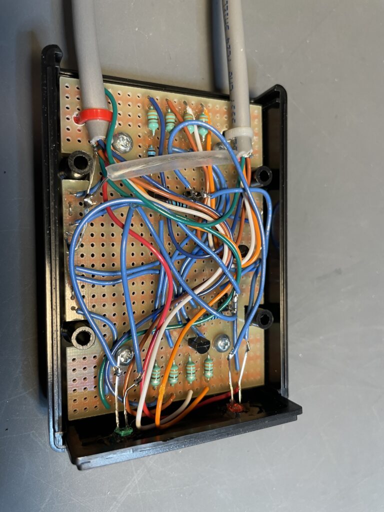
There’s the prototype board with the circuit built and now including RF chokes on the signal lines in and out (left side goes to sound card and right side goes to radio). The two-pin headers are where the LEDs will connect. The case is a Hammond unit and the proto-board is a perfect mate to it made by BusBoard Prototype Systems in nearby Calgary. A great combination!
There it is fully wired and ready for the smoke test. A metal case would be better for shielding. Maybe for the next one but this would do for now. Also for the next one some RF bypass capacitors throughout the circuit would be a good addition.
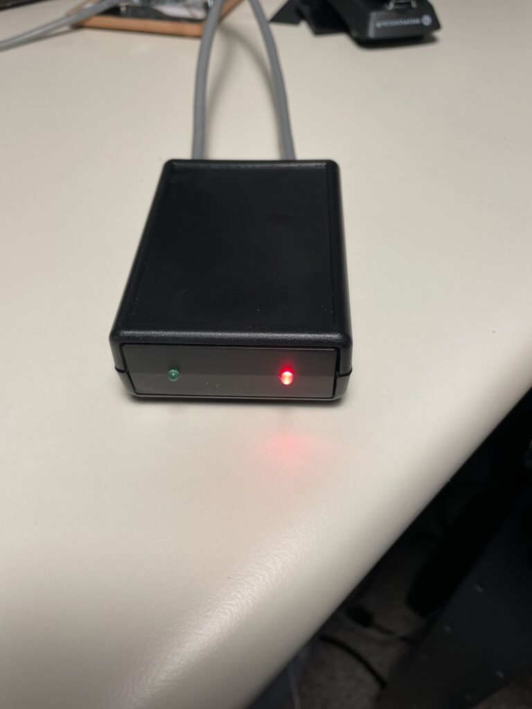
There it is done and on the air. The interface circuit can be used to connect virtually any commercial VHF or UHF radio to a CM108 sound card for use in an AllStarLink node. This was one of my goals.
Radio interface:
PTT active low
COR active low
De-bounce of 100 ms on both PTT and COR
+12 V DC power is supplied from the radio
Tx audio connected directly to sound card
Rx audio connected directly to sound card
Posted inUncategorized|Comments Off on AllStarLink node